Examples
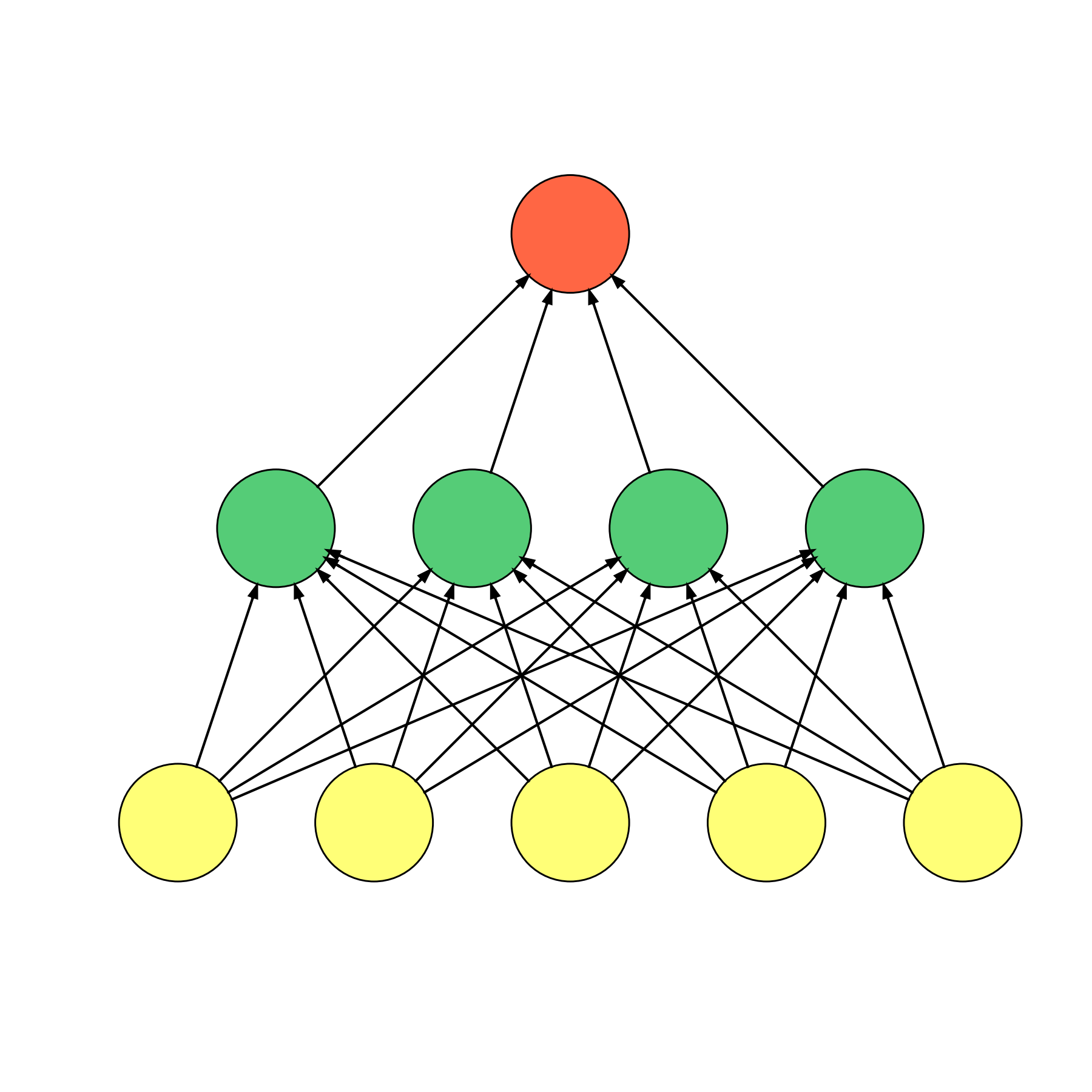
The first example is a feed forward network
import numpy as np
from viznet import connecta2a, node_sequence, NodeBrush, EdgeBrush, DynamicShow


def draw_feed_forward(ax, num_node_list):
    '''
    draw a feed forward neural network.

    Args:
        num_node_list (list<int>): number of nodes in each layer.
    '''
    num_hidden_layer = len(num_node_list) - 2
    token_list = ['\sigma^z'] + \
        ['y^{(%s)}' % (i + 1) for i in range(num_hidden_layer)] + ['\psi']
    kind_list = ['nn.input'] + ['nn.hidden'] * num_hidden_layer + ['nn.output']
    radius_list = [0.3] + [0.2] * num_hidden_layer + [0.3]
    y_list = 1.5 * np.arange(len(num_node_list))

    seq_list = []
    for n, kind, radius, y in zip(num_node_list, kind_list, radius_list, y_list):
        b = NodeBrush(kind, ax)
        seq_list.append(node_sequence(b, n, center=(0, y)))

    eb = EdgeBrush('-->', ax)
    for st, et in zip(seq_list[:-1], seq_list[1:]):
        connecta2a(st, et, eb)


def real_bp():
    with DynamicShow((6, 6), '_feed_forward.png') as d:
        draw_feed_forward(d.ax, num_node_list=[5, 4, 1])


if __name__ == '__main__':
    real_bp()
$ python apps/nn/feed_foward.py
The output is
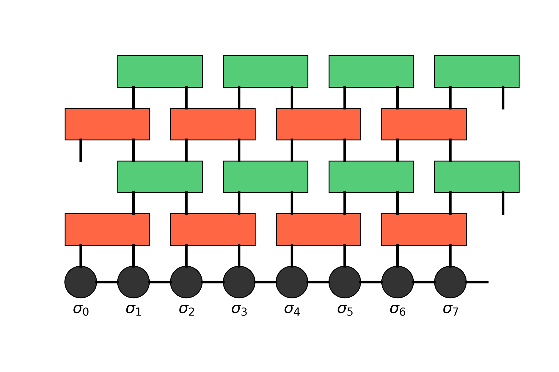
The second example is tensor network TEBD algorithm, it is also a good example to learn the grid system.
from viznet import theme, EdgeBrush, DynamicShow, Grid, NodeBrush


def tebd():
    # define a grid with grid space dx = 1, and dy = 1.
    grid = Grid((1, 1))

    # define a set of brushes.
    # NodeBrush can place a node at some location, like `node_brush >> (x, y)`,
    # and it will return a Node instance.
    # EdgeBrush can connect two Nodes (or Pin as a special Node),
    # like `edge_brush >> node_a, node_b`, and will return an Edge instance.
    size = 'normal'
    mps = NodeBrush('tn.mps', size=size)
    # invisible node can be used as a placeholder
    invisible_mps = NodeBrush('invisible', size=size)
    # define a two site mpo, which will occupy 1 column, 0 rows.
    mpo21 = NodeBrush('tn.mpo', size=size)
    edge = EdgeBrush('-', lw=2.)

    with DynamicShow((6, 4), filename='_tebd.png') as ds:
        # add a sequence of mps nodes, a store them in a list for future use.
        mps_list = []
        for i in range(8):
            mps_list.append(mps >> grid[i, 0])
            mps_list[-1].text(r'$\sigma_%d$' % i, position='bottom')
        mps_list.append(invisible_mps >> grid[i + 1, 0])

        # add mpo and connect nodes
        for layer in range(4):
            # set brush color, it will overide theme color!
            # You can set brush color to None to restore theme color.
            mpo21.color = theme.RED if layer % 2 == 0 else theme.GREEN
            mpo_list = []
            start = layer % 2
            for i, (mps_l, mps_r) in enumerate(zip(mps_list[start::2],
                                                   mps_list[start + 1::2])):
                # place an two site mpo slightly above the center of two mps nodes
                y = mps_l.position[1]+layer + 1
                mpo_list.append(mpo21 >> grid[mps_l.position[0]:mps_r.position[0], y:y])
                if layer == 0:
                    # if this is the first mpo layer, connect mps and newly added mpo.
                    pin_l = mps_l
                    pin_r = mps_r
                else:
                    # otherwise, place a pin at the top surface of previous mpo,
                    # we also require it horizontally aligned to some `mps_l` object.
                    # pin is a special node, which is zero sized,
                    # we can use it to connect nodes, add texts.
                    # if you're about to place some pin at `left` or
                    # `right` surface of a node,
                    # align is then intepreted as vertial align.
                    pin_l = mpo_list_pre[i].pin('top', align=mps_l)
                    pin_r = mpo_list_pre[i].pin('top', align=mps_r)
                if layer < 2:
                    edge >> (mps_l, mps_r)
                edge >> (pin_l, mpo_list[-1].pin('bottom', align=mps_l))
                edge >> (pin_r, mpo_list[-1].pin('bottom', align=mps_r))
            mpo_list_pre = mpo_list


if __name__ == '__main__':
    tebd()
$ python apps/tn/tebd.py
The output is
The third example is a quantum circuit
import matplotlib.pyplot as plt
from viznet import DynamicShow, QuantumCircuit
from viznet import parsecircuit as _


def ghz4():
    '''4 bit GHZ circuit, applicable on ibmqx4 circuit.'''
    num_bit = 4
    with DynamicShow((5, 3), '_exact_ghz4_circuit.png') as ds:
        handler = QuantumCircuit(num_bit=4, y0=2.)
        handler.x += 0.5
        handler.gate(_.GATE, 0, 'X')
        for i in range(1, num_bit):
            handler.gate(_.GATE, i, 'H')
        handler.x += 1
        handler.gate((_.C, _.NOT), (1, 0))
        handler.gate((_.C, _.NOT), (3, 2))
        handler.x += 0.7
        handler.gate((_.C, _.NOT), (2, 0))
        handler.x += 0.7
        handler.gate((_.C, _.NOT), (3, 2))
        handler.x += 1
        for i in range(num_bit):
            handler.gate(_.GATE, i, 'H')
        handler.x += 1
        for i in range(num_bit):
            handler.gate(_.MEASURE, i)
        handler.edge.style = '='
        handler.x += 0.8
        for i in range(num_bit):
            handler.gate(_.END, i)

        # text |0>s
        for i in range(num_bit):
            plt.text(*handler.get_position(i, x=-0.5), r'$\left\vert0\right\rangle_{Q_%d}$' %
                     i, va='center', ha='center', fontsize=18)


if __name__ == '__main__':
    ghz4()
$ python apps/qc/ghz.py
The output is
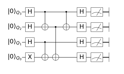
Here, we used the QuantumCircuit instance handler to help us build the circuit.
gate method of handler take brush(es) as first argument and line(lines) as second argument.
handler.x decide the x axis of this gate.